Automotive PCB Assembly: From Design to Mass Production
Automotive electronics have transformed modern vehicles into intelligent, connected systems. Every innovation relies on automotive PCB assembly, from safety features like airbags and anti-theft sensors to infotainment systems and climate control. But for printed circuit board assembly manufacturers, the challenge is not just building a functional automotive circuit board—it’s optimizing the full journey from PCB design to mass printed circuit board production with reliability, compliance, and cost-efficiency.
This guide provides a step-by-step overview of the automotive printed circuit board assembly process, key standards, and quality considerations that matter most to automotive OEMs, ODMs, and Tier-1 suppliers.
Key Features of Automotive PCB Assembly
Why Automotive Electronics PCBA board is Different
Unlike consumer electronics, automotive electronics printed circuit assembly must endure:
1. Adaptability to Extreme Environments
- Temperature Resistance
-
- Operating Range: -40°C to 150°C (Short-term Engine Compartment Temperatures Up to 200°C)
- Using a high-Tg PCB substrate (Tg ≥ 170°C); the polyimide substrate can withstand temperatures up to 260°C
- Mechanical Stress Resistance
- Required to withstand 1 million vibration cycles (equivalent to 200,000 km of driving).
- Through-hole copper thickness ≥ 25μm; solder joints must pass a 20G acceleration shock test.
2. Reliability Circuit Design Standards
- Life Requirements
- Designed lifespan: 15 years/200,000 kilometers, failure rate below 10 ppm
- Passed 85°C/1000-hour aging test and thermal cycling test
- Safety Protection
- Complies with ISO 26262 functional safety standards, with a DFMEA failure database established
- Conformal coating (25-75μm) for moisture and salt spray resistance, and EMC design to suppress electromagnetic interference
3. Automotive PCB materials and Process Innovation
- Substrate Upgrade
- Thick copper design (70-105μm) reduces high-current heat generation
- Aluminum substrate Used in critical heat dissipation areas (such as the battery management system).
- Surface Treatment
- Lead-free solder (SAC305) with a melting point of 217°C, and gold-plated pads for oxidation protection.
- Immersion gold (IG) technology (≥3μm) ensures high-temperature contact stability.
4. Automotive PCB Board Assembly Manufacturing and Testing Standards
- Line width/space accuracy ≤ 0.0762mm, impedance tolerance ±5%.
- Verified by salt spray testing, ESD testing, and 1000 temperature cycles.
These features enable automotive circuit board to maintain stable operation for 15 years in complex environments such as vibration, temperature fluctuations, and corrosion, far exceeding the performance limits of consumer electronics.
From PCB Board Design to Prototyping Circuit Board
Automotive PCB Design Optimization Principles
1. Component Layout Design
- Current Path Optimization: Arrange components based on conduction paths and current flow, isolating high-frequency signals from power components. High-current devices are prioritized near the power input.
- Signal Isolation: High-frequency signal traces should be ≥3mm away from power components, and sensitive analog circuits should be isolated in separate areas.
- Heat Dissipation Design: Distribute heat-generating components, using aluminum PCB substrates or thick copper (70-105μm) for enhanced heat dissipation; add heat sinks for high-power components.
- Safety Clearance: Insulation resistance >100MΩ for high-voltage circuits (>24V), exposed copper width <0.5mm in the gold finger area.

2. Electromagnetic Compatibility Design
- Grounding System: Use a tiered design with at least 4 layers, with a power/ground plane spacing ≤0.2mm.
- Differential Wiring: Impedance control: 100Ω ±10%, with equal length tolerance <5mil.
- Filtering Design: Implement a π-type filter network (10μF + 0.1μF capacitance combination) at the power input.
3. Thermal Management Solution
- Base Material Selection: Aluminum substrate with a thermal conductivity of ≥2.0 W/m·K, with copper substrates in selected areas.
- Heat Dissipation Structure:
- 6oz thick copper design (current density ≤3 A/mm²)
- Thermal via array (0.3mm diameter, 2mm pitch)
- Heat sink contact area ≥150% of the device bottom area.
4. Safety Specifications
- High-voltage Protection
- Creep distance ≥8 mm/kV
- Hypovoltage test 1500 VAC/1 min
- Mechanical Strength
- Solder joint shear resistance ≥5%
- Through-hole copper thickness ≥25 μm
Automotive PCB Preparation Process
1. Automotive PCB Substrate Materials Preparation
- Substrate Procurement
- Select specially modified FR-4 or flexible laminates that meet IATF16949 standards.
- High-Tg FR-4 (Tg ≥170°C) or polyimide (temperature resistance 260°C).
- Copper Foil: Thick copper design (6oz) reduces heat generation due to high current.
- Polyimide substrate: temperature resistance of 260°C, dielectric constant of 3.2, suitable for use in high-temperature areas of the engine compartment
- Electronic Component Selection
- Use AEC-Q100/200 certified components with a wide operating temperature range of -40°C to 125°C.
- Incoming Inspection: Full inspection of appearance and electrical parameters, with defective product rate controlled below 10 ppm.
2. Process Document Preparation
- Establish a DFMEA failure mode database and develop IPC-A-610E standard operating instructions.
- Design dedicated impedance test strips (three each of microstrip and stripline, length ≥ 200 mm).
Automotive PCBA Manufacturing Process
1. Surface Mount Technology Process
- Solder Paste Printing
Using a high-precision laser stencil (±0.0762mm) to print solder paste, SPI inspects solder paste thickness (25-75μm) and coverage (≥75%). - PCB Board Component Placement
0201 component placement accuracy <0.05mm, BGA solder joint void rate <3%, using a multi-spectral vision alignment system. - Reflow Soldering
Nitrogen-shielded reflow oven, peak temperature 260°C ±5°C, temperature profile control ±2°C.
2. DIP Insertion Process
- Soldering Inspection
3D SPI inspection of solder paste coverage, X-ray confirmation of solder penetration depth >50% - Wave Soldering
Selective wave soldering is used, with a solder joint penetration depth >50% and pin bending resistance tested to 5N. - Post-soldering Processing:
Manual re-soldering of key components and pin trimming with a soldering iron. - Cleaning and PCB Board Testing
Ultrasonic cleaning removes flux residue, and AOI inspects soldering quality.

3. Conformal Coating
- Coating Process
Conformal coating thickness 25-75μm, moisture and salt spray resistant, 85°C/1000-hour aging test - Curing Conditions
Curing for 5 hours at room temperature, humidity <75%, temperature >16°C
4. Box Build Assembly
- Mechanical Assembly
Installs heat sinks, housings, and other structural components with ±5% torque control accuracy. - Wiring Harness Connection
Uses automotive-grade connectors with contact resistance <50mΩ.
5. Testing and Inspection
- Functional Testing
System-level verification according to ISO 26262
In-Circuit Testing (ICT)
FCT testing of input and output parameters
Functional testing of the airbag control unit, air conditioning, and infotainment systems
Reliability aging testing under thermal cycling - Environmental Testing
85°C/85% humidity for 1000 hours, 20G vibration testing, and salt spray corrosion testing - Reliability Testing
-40°C to 125°C temperature cycling for 2000 cycles - Electrical Testing
On-resistance <50mΩ, insulation resistance >100MΩ
6. Mass Circuit Board Car Production Optimization
- Optimized stencil aperture design
Lean manufacturing reduces costs and ensures scalability - Improved yield
Defect rates are kept below 10ppm, and blockchain technology is used for full process traceability - Cost optimization
Reduced material waste through design-for-manufacturing (DFM) analysis and optimized placement paths improve efficiency.

Applications of Automotive PCBs and PCBAs
1. Automotive PCB in Airbag Control
As a safety-critical component, the airbag PCB board fabrication must meet the highest ASIL-D safety level requirements. It utilizes double layer PCB redundant design (basic function board + extended function board), achieving active and passive safety convergence through independent connectors.Key features include:
- Passes 15G mechanical shock testing
- Insulation resistance ≥ 10¹²Ω
- Fault isolation capability 99.9%
- Adopts a safety island architecture with a physical isolation band width of 0.5mm
2. Automotive PCBA in Climate Control
The air conditioning control printed circuit manufacturing needs to achieve a temperature adjustment accuracy of ±0.5°C and utilizes a high-precision sensor interface circuit design. Typical Application Features:
- Supports PWM speed control (1% accuracy)
- Integrated CAN bus communication interface
- Operating temperature range -40°C to 105°C
- Uses thick copper design (2oz) for enhanced heat dissipation
3. Infotainment Systems (Flexible PCB for Displays and Media)
The in-vehicle infotainment system utilizes flexible PCBs to facilitate complex center console wiring, meeting the demands of 4K/8K video transmission. Technical Highlights:
- Supports 5G/millimeter wave antenna integration
- Impedance control of ±5Ω (differential pair)
- Bending radius ≥ 10mm
- Tested for 1 million bends
4. Digital Displays PCB (instrument clusters, HUDs)
The instrument cluster/HUD display printed circuit board manufacturering utilizes HDI technology for high-density wiring. Key specifications include:
- Minimum line width/spacing 0.0762mm
- Supports 10-bit color depth
- Operating temperature -30°C to 85°C
- Anti-electromagnetic interference design (EMI shielding layer)
5. Lighting System PCB
The LED headlights utilize an aluminum-based PCB (IMS) for efficient heat dissipation. Typical specifications:
- Thermal conductivity: 1.5W/m·K
- Copper layer thickness: 2oz
- V withstand voltage: 500V
- IP67 certified

Substrates and Materials for Automotive PCB Assembly
1. Aluminum PCB Board Production for automotive applications
This aluminum-based PCB (IMS) is specifically designed for LED headlights. It utilizes a 1.5W/m·K high thermal conductivity aluminum substrate with a 2oz (70μm) copper layer. It has passed 500V withstand voltage testing and is IP67 certified. Typical heat dissipation designs include:
- A heat dissipation area of ≥100mm² per watt of power consumption
- an array of 0.3mm φ heat dissipation vias (1.2mm spacing) on the bottom of the high-power LED
- a star-shaped routing topology to minimize voltage drop accumulation
2. Ceramic PCB manufacturer for High-Temperature Automotive
Powertrain PCBs utilize ceramic substrates (such as Al₂O₃/AlN). Key features include:
- Temperature range -55°C to 300°C
- Thermal conductivity 90-170 W/m·K
- Dielectric strength >15 kV/mm
- ISO 26262 functional safety certification
3. Thick Copper FR4 – General Automotive PCBs
Thick copper FR4 substrates (2-6 oz) are suitable for high-current applications such as BMS. Technical specifications:
- High heat-resistant substrate with a Tg ≥ 170°C
- Copper thickness 105 μm (3 oz) or greater
- Impedance control ±5 Ω
- Passes 85°C/1000-hour aging test
4. Polyimide Flexible PCBs – Infotainment and Digital Displays
Flexible PCBs utilize Kapton polyimide substrate. Key process requirements:
- Minimum line width/space ≥ 75 μm
- Bend radius ≥ 10 mm
- Passes 1 million-cycle bend test
- ENIG (nickel-gold) surface treatment
Automotive PCB Assembly Standards and Certifications
1. IPC standards for Automotive PCB Assembly and Manufacturing
- IPC-6012DA
A rigid printed circuit board qualification standard specifically developed for automotive applications. It requires an annular ring thickness of ≥ 0.05mm, a through-hole copper thickness of ≥ 25μm, and a 1 million-cycle vibration test. - IPC-A-610
A car PCB board assembly acceptability standard that specifies a solder joint void rate of <3% (BGA), a 0201 component placement tolerance of <0.05mm, and a solder mask coverage tolerance of ±0.1mm.
2. IATF 16949 Automotive Printed Circuit Board Assembly Reliability
- Certification Requirements
Tier-one automotive electronic assembly suppliers must be IATF 16949 certified, with a process capability index (CPK) ≥ 1.33 and 100% SPC control coverage for key processes. - Reliability Verification
- 85°C/1000-hour burn-in test
- 2000 temperature cycles (-40°C to 125°C)
- 1 million vibration cycles (equivalent to 200,000 kilometers
3. ISO 9001 Automotive PCB Assembly Quality Management System
- System Requirements
Establish a systematic quality management process, including DFMEA failure mode analysis, 8D problem-solving mechanism, and continuous improvement plan. - Critical Control Points
- Incoming material inspection pass rate ≥ 99.95%
- Process defect rate ≤ 100 ppm
- Outgoing inspection AQL ≤ 0.65

Choosing the Right Automotive PCB Assembly Manufacturer
When selecting an automotive circuit board manufacturer, business clients should look for:
Experience in automotive projects (proven track record in mass production)
Transparent cost structures (no hidden charges in logistics or assembly)
Advanced testing capability (AOI, ICT, thermal shock testing)
Compliance certifications (IATF 16949, ISO 9001, IPC-A-610)
Global supply chain support for reliable component sourcing
Get A Quote Online
The journey from automotive PCB design to mass production assembly requires not only precision and compliance, but also a reliable manufacturing partner you can trust. Whether you are developing next-generation EV power modules, durable car circuit boards for safety systems, or cost-effective auto PCBs for infotainment, the right partner makes all the difference.
At SCSPCBA, we combine expertise, advanced facilities, and strict adherence to automotive PCB standards (IATF 16949, ISO 9001, IPC-A-610) to deliver boards that meet the highest quality and reliability expectations of the automotive industry.
Contact us today to discuss your project and request a tailored automotive PCB assembly quote.
Latest News
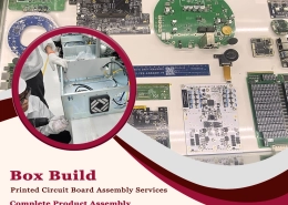
 Box Build Printed Circuit Board Assembly Services | Complete Product AssemblyFebruary 25, 2026 - 1:00 am
 PCB Assembly from Prototype to Mass Production: Solving Volume Challenges for ODM/OEMFebruary 10, 2026 - 1:00 am
 PCB Assembly Testing & Inspection: Building Trust Through Measurable Quality ControlFebruary 5, 2026 - 1:00 am
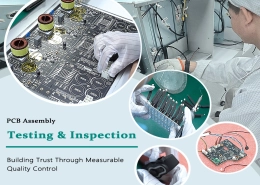
 From Prototype to Mass Production: Consumer Electronics PCB AssemblyJanuary 30, 2026 - 1:00 am
 Industrial Control PCBA Solutions With Strict DFM and MES ControlJanuary 25, 2026 - 1:00 am
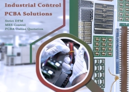