PCBA Functional Testing Explained: The Key to Performance and Reliability
PCBA Functional Test (FCT) is a testing process for overall functional verification of the one-stop printed circuit board assembly manufacturing. It aims to simulate the actual working environment and ensure the integrity and reliability of the collaborative work of software and hardware.
Why PCBA Functional Testing Is the Final Guard of Quality Control
In modern electronic manufacturing, PCBA functional testing (FCT) represents the final and most critical stage of the quality assurance process. It is not just a simple pass/fail inspection, but a comprehensive evaluation that determines whether the assembled board can reliably deliver its intended performance in real-world applications.
1. Design Verification — Turning Design Intent into Functionality
Functional testing validates whether the PCBA design performs as expected across its core operating domains—including power management, signal processing, data communication, and user interface control.
This step ensures that the design intent translates accurately into real functionality, confirming that hardware and embedded software operate harmoniously within system specifications.
2. Defect Interception — Catching Hidden PCB Assembly and Manufacturing Faults
Even after advanced SMT circuit board and optical inspections, hidden manufacturing defects may remain—such as cold solder joints, misplaced components, or incorrect component values.
Through FCT, these latent faults can be identified under simulated working conditions, preventing defective circuit boards from reaching the customer.
When integrated with In-Circuit Testing (ICT) earlier in the circuit board manufacturing process, it forms a dual defense mechanism: ICT isolates component-level issues, while FCT validates system-level functionality.
3. Reliability Evaluation — Beyond Performance, Toward Durability
A truly reliable printed circuit assembly must sustain performance across varying temperatures, humidity, and vibration environments.
Functional testing often incorporates environmental stress simulation, ensuring that circuits maintain stability under real-life conditions such as high-temperature operation or mechanical vibration.
This not only improves circuit on board durability but also provides predictive insights into long-term reliability and lifecycle performance.
Testing Stages Across the PCBA Lifecycle: Integrating ICT and FCT
PCB fabrication and assembly testing is not limited to a single point in production; it evolves alongside the product lifecycle. Both In-Circuit Testing (ICT) and Functional Circuit Testing (FCT) play critical roles across different stages—from early prototyping to post-repair validation.
1. Research and Development (R&D) Stage — Prototype Functional Validation
At the early design stage, FCT takes the lead. Engineers perform first-version PCB board sample testing to verify the functionality of critical modules, such as the main controller, power circuitry, and signal interfaces.
This ensures that the PCB layout, firmware, and system logic meet design expectations before moving into pilot production.

2. Mass PCB Board Production Stage — Automated Quality Assurance
During volume PCB board fabrication, both ICT and FCT are used in tandem.
- ICT ensures early fault detection at the component and solder joint level.
- FCT, often executed via Automated Test Equipment, performs batch or full functional testing under simulated load conditions.
This dual-layer testing ensures that every PCBA leaving the production line complies with factory acceptance standards, improving the overall first-pass yield and reducing post-delivery failures.
3. Rework and Maintenance Stage — Post-Repair Reliability Testing
After a defective PCBA circuit board is reworked or repaired, a secondary round of ICT and FCT is essential.
- ICT confirms that re-soldered electronic parts are properly connected
- FCT verifies that the repair did not introduce new issues and that the PCB and assembly can still perform reliably within operational limits.
By standardizing these testing phases across the PCB manufacturing assembly lifecycle, printed circuit board assembly manufacturers can establish a closed-loop quality system, ensuring consistent reliability from PCB prototype to production to after-sales service.
FCT vs ICT: The Core Differences Between Two Key Test Methods
| Category | FCT (Functional Circuit Test) | ICT (In-Circuit Test) |
|---|---|---|
| Purpose | Validates system-level functionality under real conditions | Checks electrical connections and components parts individually |
| Testing Stage | After full PCBA assembly | After SMT or THT stage |
| Test Content | Software logic, signal response, power output, interface communication | Shorts, opens, resistors, capacitors, diode polarity, etc. |
| Advantages | Simulates real operation, ensures system performance | High precision fault localization, early defect screening |
| Limitations | Requires custom fixture and firmware, slower | Cannot verify system-level logic or firmware behavior |
For high-reliability applications such as automotive control modules, medical devices, and power management systems, combining ICT + FCT forms a double-layer quality defense, ensuring both component-level and system-level reliability.
Commonly Used Printed Circuit Assembly Test Equipment
PCBA manufacturing testing equipment uses electrical, welding, and environmental reliability methods to detect solder joint quality, environmental adaptability, and functional reliability. Typical equipment is as follows:
1. Electrical performance test equipment
- ICT in-circuit tester
Uses metal probes to connect to pads to detect circuit opens/shorts and component parameter deviations - FCT test platform
Combined with a fixture and test flow, it simulates the box build assembly product’s operating state and supports the acquisition of parameters such as voltage, current, and timing.
2. Assembly Soldering Quality Inspection Equipment
- Automated Optical Inspection (AOI)
Using vision algorithms, it detects component misalignment, polarity errors, and solder bridge defects, with an inspection accuracy of ±25μm. - X-ray Inspection Equipment:
Can penetrate BGA/QFN packages to inspect solder joint void rates (standard requirement ≤25%), solder joint bridging, and cold solder joints, with a minimum defect detection capability of 0.5μm. It can also analyze the internal solder joint quality of multi-layer PCBs.
3. Environmental Reliability Testing Equipment
- Temperature Cycling Chamber
Complies with IEC 60068-2-14 standards, simulating extreme temperature fluctuations from -40°C to 125°C, with up to 1000 cycles. For example, automotive electronics assembly PCB requires 1000 cycles to verify solder joint thermal stress tolerance. - Vibration Test Bench
Complies with MIL-STD-810G standards, with a frequency range of 5Hz-2000Hz, simulating the mechanical vibration environment experienced during transportation or operation. For example, a new energy vehicle BMS module failed the vibration test, resulting in connector loosening.

PCB Manufacturing Assembly Testing International Industry Standards
Circuit board assembly testing must follow multi-level standards, covering the entire process of design, manufacturing, and acceptance. The core standards are as follows:
1. IPC series standards (core standards for the electronics assembly industry)
(1) IPC-A-610:Acceptability of Electronic Assemblies
-
Scope: Globally recognized standard for assessing the appearance and solder quality of printed circuit board assembly manufacturing.
-
Key Contents:
- Soldering joint assembly quality requirements (wetting, hole filling, bridging, etc.)
- Component mounting orientation, polarity, and clearance requirements
- Classified as Class 1 (general electronics), Class 2 (high-reliability commercial electronics), and Class 3 (mission-critical equipment, such as aerospace/medical equipment).
- Test Applications: Automated Optical Inspection (AOI), visual inspection, and FCT acceptance criteria.
(2) IPC-9252: Requirements for Electrical Testing of Printed Boards
-
Scope of application: Electrical connectivity testing of PCBs and PCBAs (ICT testing phase).
-
Key points:
- Opens, shorts, and impedance consistency
- Test point layout and fixture design requirements
- Electrical performance verification methods (e.g., flying probe testing, bed-of-nails testing)
(3) IPC-TM-650: Test Methods Manual
-
Scope: Specifies physical, chemical, and electrical test methods for PCB board fabrication or printed circuit board assembly.
-
Key Contents:
- Insulation resistance, dielectric strength
- Thermal cycling, peel strength
- Pad adhesion and cleanliness testing
(4) IPC-2221 / 2222:Generic Standard on Circuit Board Design
- Scope: Guides PCB design rules, signal line spacing, insulation thickness, and via design.
- Provides a design basis for Design for Testability (DFT) for functional testing.
(5) IPC-J-STD-001:Requirements for Soldered Electrical and Electronic Assemblies
- Scope: Specifications for soldering procedures and materials, including solder types, flux, and cleaning requirements.
- Serves as a standard reference for surface-mount circuit boards and subsequent reliability testing.
2. ISO & IATF Quality System Standards
(1) ISO 9001: Quality Management System
-
Scope of Application: General quality system framework, ensuring traceability and consistency from design to shipment.
-
Application in PCB assembly services:
- Test Data Recording and Tracking
- Defective Product Analysis and Continuous Improvement Process
(2) IATF 16949:Automotive Quality Management System
-
Scope of Application: Quality management standards for automotive electronics products (including automotive PCBAs).
-
Texting Content:
- Test Equipment Calibration, Measurement System Analysis (MSA)
- PPAP (Production Part Approval Process)
- FMEA (Failure Mode Analysis)
- SPC (Statistical Process Control)
- Implications for PCBA Testing: Requires traceability throughout the entire testing process, and requires verification and revalidation of test fixtures and procedures.
(3) ISO 13485: Medical Device Quality Management System
-
Scope of application: Medical electronic PCBA manufacturing.
-
Texting Content:
- Traceability
- Functional test record archiving and verifiability
3. UL Reliability and Safety Standards
(1) UL 796 & UL 60950 / UL 62368: Safety Standards for Printed Wiring Boards
-
Scope: Electrical safety and fire protection standards.
-
Texting Content:
- PCB material flame retardancy rating (e.g., UL94V-0)
- Insulation distance and dielectric strength requirements
- Significance: FCT and final factory inspection must ensure that assembly electronics meet safety regulations.

Common Troubleshooting for Printed Circuit Board Testing
1. Soldering Faults
(1) False Solder Joints
-
- Symptom: Unstable function, sometimes working and sometimes not
- Cause: Insufficient solder, uneven temperature, or oxidized component pins
- Solution: Resolder or resolder with a hot air gun to clean the oxide layer
- (2) Solver Bridging (Short Circuit)
- Symptom: Continuity between adjacent pins
- Solution: Clean with desoldering tape or repair with a soldering iron
- Inspection: Automated Optical Inspection (AOI) visual inspection, adjust the reflow oven temperature profile, pre-bake components, and quickly identify cosmetic defects
2. Electronic Components Parts Failures
(1) Component Damage
-
- Symptom: Breakdown, burnout, no output
- Cause: Overvoltage, overcurrent, static electricity, or aging
- Solution: Functional test, replace damaged components, optimize storage environment, and verify overall functionality
(2) Reverse Polarity
-
- Symptom: Capacitor bulge, chip overheating
- Solution: Correct polarity according to markings and resolder
3. Circuit Faults
(1) Short Circuit
-
- Detection Method: Multimeter resistance measurement, X-ray inspection of the multilayer board interior
- Handling: ICT online testing to identify design flaws, repair circuits or replace components to pinpoint the fault
(2) Open Circuit
-
- Symptom: Signal interruption, no voltage
- Solution: Flying leads or re-drilling
4. Environmental and Signal Failures
(1) Moisture/Contamination
-
- Symptom: Current leakage, performance degradation.
- Solution: Ultrasonic cleaning and drying, and application of conformal coating.
(2) EMI Interference
-
- Symptom: Signal distortion, false triggering.
- Solution: Add a shielding cover and optimize grounding design.

Case Study: Discovering Potential Soldering and Component Failures Through PCBA Testing
During a batch test of automotive pcb assembly and manufacturing control boards, the initial pass rate reached 99%. However, after delivery, customers reported frequent Wi-Fi disconnections in high-temperature environments. Repair analysis pointed to communication anomalies with the main control chip, but routine functional testing revealed no faults.
1. Key Turning Point: Locking Abnormality in the Simulated Environmental Test Rig
Engineers used a customized PCBA test rig to simulate high-temperature cycling tests. When the ambient temperature rose to 65°C, the test rig detected abnormal impedance fluctuations in the MLCC capacitor (number C107) adjacent to the main control chip. Disassembly revealed the following:
- Soldering Hazard: A localized cold solder joint existed at the bottom of the capacitor, and thermal expansion at high temperatures caused periodic fractures in the solder joint.
- Mechanical Stress Damage: A cross-section revealed a microcrack (approximately 20μm) in the upper right corner of the capacitor’s ceramic body, coinciding with a stress concentration point where the BTB connector is fastened during assembly.
2. Root Cause Tracing: Double Failure Chain
- Design Flaw: Improper alignment of capacitor pads and PCB traces (small pads + thick traces). During reflow, solder was absorbed by the trace surface, resulting in shrunken solder joints.
- Process Out-of-Control: The screw-locking process on the production line caused PCB deformation of 35μm, resulting in coplanarity deviation of stacked components (maximum pin drop of 54.89μm), which in turn caused microcracks.
3. Solution and Results
- Optimized test fixture: Added a high-temperature vibration module to actively stimulate cold solder joint failures.
- Process Improvement: Adjusted the BTB fastening sequence to reduce local stress.
- Design Change: Re-matched the capacitor pad to trace ratio.
Without FCT testing, this potential risk could cause a power outage or control failure during vehicle operation.
Through statistical analysis and traceability of failure data, the production line promptly optimized the reflow soldering temperature profile and placement pressure settings, increasing the yield from 98.3% to 99.8% while also reducing customer returns.
Improve Printed Circuit Board Production Shipment Qualification Rates Through Scientific Testing Processes
An efficient PCBA testing process typically includes the following steps:
- ICT online inspection – Quickly detects opens, shorts, and component defects
- AOI visual inspection – Verifies placement orientation and solder joint consistency
- FCT functional testing – Simulates real-world operating conditions for performance verification
- Aging and environmental stress testing – Verifies long-term stability
- Final inspection and data traceability – Full process records ensure traceability
Through digital test data management and automated inspection systems, PCB assembly manufacturers can:
- Accurately track defect causes;
- Closing the loop on quality issues;
- Integrate test results with the MES system for real-time quality control.
PCBA Testing Is The “Invisible Shield” of Manufacturing Reliability
With increasingly fierce competition in the smart manufacturing and electronics industries, printed circuit assembly functional testing is no longer an option but a strategic core for quality assurance.
From ICT to FCT to reliability verification, every step safeguards final product performance.
Only through a scientific, systematic, and standardized testing system can companies achieve the optimal balance between shipment volume and quality, earning market trust and long-term partnerships.
Latest News
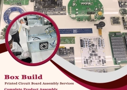
 Box Build Printed Circuit Board Assembly Services | Complete Product AssemblyFebruary 25, 2026 - 1:00 am
 PCB Assembly from Prototype to Mass Production: Solving Volume Challenges for ODM/OEMFebruary 10, 2026 - 1:00 am
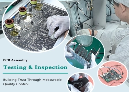
 PCB Assembly Testing & Inspection: Building Trust Through Measurable Quality ControlFebruary 5, 2026 - 1:00 am
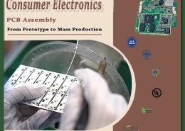
 From Prototype to Mass Production: Consumer Electronics PCB AssemblyJanuary 30, 2026 - 1:00 am
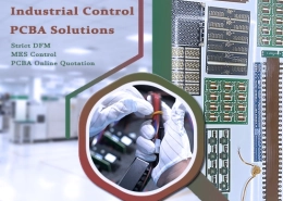
 Industrial Control PCBA Solutions With Strict DFM and MES ControlJanuary 25, 2026 - 1:00 am