High-frequency PCB

High-Frequency PCB Manufacturing Process

Material Selection – Choosing specialized laminates with low dielectric constant (Dk) and low loss tangent, such as PTFE (Teflon) or ceramics, to minimize signal attenuation.

Layer Stacking – Carefully stacking layers with controlled impedance to maintain signal integrity.

Copper Lamination – Bonding copper foil to the substrate material with high precision for reliable electrical conductivity.

Etching & Imaging – Using photolithography and advanced etching to create fine traces while minimizing signal distortion.

Drilling – High-precision drilling for vias to ensure effective electrical connections.

Surface Treatment – Applying finishes like ENIG or OSP to enhance solderability and reduce signal degradation.

Testing & Inspection – Rigorous testing for electrical performance and high-frequency signal reliability.

PCB Fabrication Services

High-frequency PCB

High-frequency PCB board fabrication

Manufacturing Features of High-frequency PCB

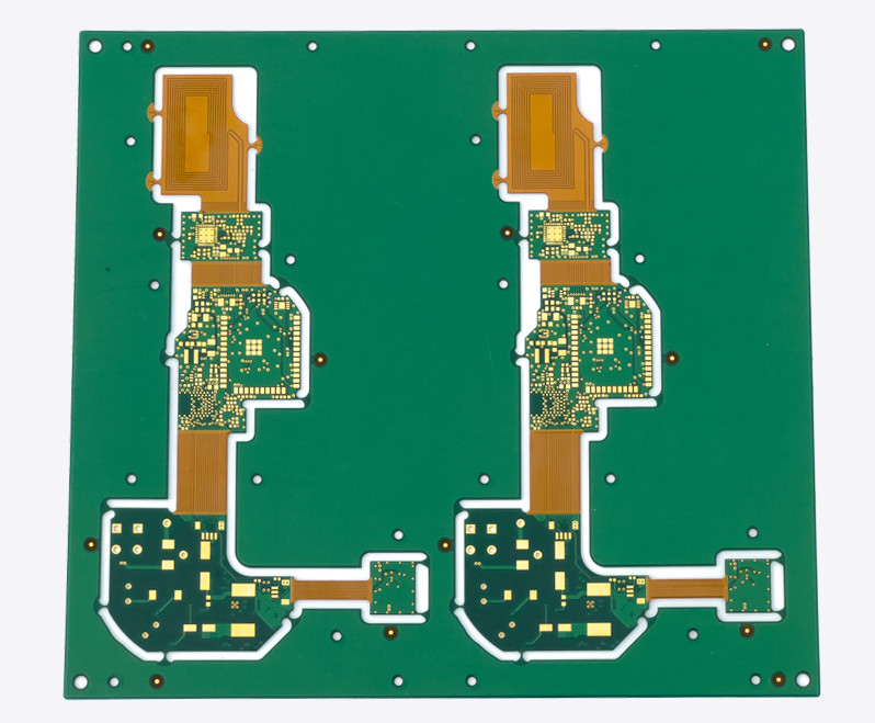
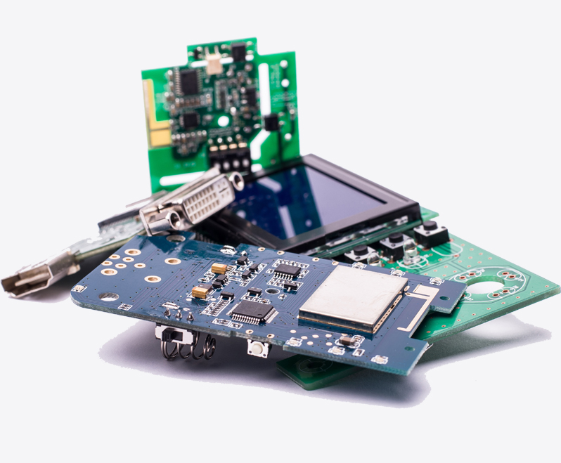
High-frequency PCBs are designed with materials like PTFE or ceramics to minimize signal loss and ensure high-speed signal integrity. The manufacturing process includes precise layer stacking, copper lamination, fine etching, and high-precision drilling. These PCBs are ideal for RF communication, satellite systems, and high-speed data processing, providing reliable performance in demanding, high-frequency applications.

High-frequency PCB Application Areas

High-frequency PCBs are vital in wireless communication (5G, Wi-Fi 6E), automotive electronics (ADAS, V2X), medical equipment (MRI, biosensors), industrial control (IIoT, automation), and defense/aviation (radar, satellites). They offer low loss, precise impedance control, and high reliability, enabling high-speed data transmission, signal integrity, and stability in extreme environments. These PCBs support miniaturization, high power, and efficient signal processing, driving advancements in global connectivity, smart technologies, and mission-critical systems.

SCSPCBA’s High-Frequency Circuit Board Manufacturing Capabilities

Advantages of the High-Frequency PCB Manufacturer
Manufacturing CapabilitiesSpecifications
RF PCB layer quantity2 to 24Minimum line width/line spacing 2.5mil/2.5mil
High-frequency PCB types6GHz to 24GHz PCB, 70GHz PCB, embedded antenna PCB, ceramic high-frequency PCB, PTFE high-frequency PCB, Rogers PCBMinimum aperture0.15mm
Finished PCB thickness
0.5mm, 0.8mm, 1.0mm, 1.2mm, 1.6mmDielectric constant (Dk) 2.2~3.5 (common high-frequency material range)
Base copper thickness
Normally 0.5oz and 1.0ozDissipation factor (Df) 0.0009~0.005
Conductor width control
±0.02mmSurface treatment ENIG, OSP, LFHASL, gold plating, nickel-palladium-gold, etc.
Maximum impedance control tolerance2%Impedance control accuracy ±5%
PCB vias we can drillBlind via, overlapping via, staggered via, skip via, buried viaHigh frequency test Time domain reflection test (TDR), network analyzer test
Thermal stress
10 seconds at 288°CInter-layer alignment accuracy ±50μm
Hole wall copper thickness

≥ 20μм
Surface finish 0.1μm~0.4μm
Punching or routing tolerance±0.10mm to 0.13mmSolder mask thickness on traces
20μm to 30μm
Solder mask ink
Taiyo PSR4000, Tamura DSR2200High frequency test capability TDR, VNA (vector network analyzer), thermal shock test, etc.

AI Intelligent Online Quotation

PCB Services

PCBA Service

BOM Services

Recommended Services

PCB Fabrication Services

Components Services

PCB Assembly Services

Box Build Assembly Cases

Solution Development

From prototype to production – find the best electronics manufacturing services

Start Your Project with SCSPCBA

©Copyright 2025 SCS | All Rights Reserved |